ASR6601 Tremo Programmer Tool User Guide
Introduction
About This Document
This document mainly introduces the Tremo Programmer Tool for developers to download files into the Flash of LPWAN SoC ASR6601.
Included Chip Models
The product models corresponding to this document are as follows.
Model |
Flash |
SRAM |
Core |
Package |
Frequency |
|---|---|---|---|---|---|
ASR6601SE |
256 KB |
64 KB |
32-bit 48 MHz Arm China STAR-MC1 |
QFN68, 8*8 mm |
150 ~ 960 MHz |
ASR6601CB |
128 KB |
16 KB |
32-bit 48 MHz Arm China STAR-MC1 |
QFN48, 6*6 mm |
150 ~ 960 MHz |
ASR6601SER |
256 KB |
64 KB |
32-bit 48 MHz Arm China STAR-MC1 |
QFN68, 8*8 mm |
150 ~ 960 MHz |
ASR6601CBR |
128 KB |
16 KB |
32-bit 48 MHz Arm China STAR-MC1 |
QFN48, 6*6 mm |
150 ~ 960 MHz |
Copyright Notice
© 2021 ASR Microelectronics Co., Ltd. All rights reserved. No part of this document can be reproduced, transmitted, transcribed, stored, or translated into any language in any form or by any means without the written permission of ASR Microelectronics Co., Ltd.
Trademark Statement
ASR and ASR Microelectronics Co., Ltd. are trademarks of ASR Microelectronics Co., Ltd.
Other trade names, trademarks, and registered trademarks mentioned in this document are the property of their respective owners and are hereby declared.
Disclaimer
ASR does not give any warranty of any kind and may make improvements and/or changes in this document or in the product described in this document at any time.
This document is only used as a guide, and no contents in the document constitute any form of warranty. Information in this document is subject to change without notice.
All liability, including liability for infringement of any proprietary rights caused by using the information in this document, is disclaimed.
Revision History
Date |
Version |
Release Notes |
|---|---|---|
2020.05 |
V0.1.0 |
First release. |
2020.09 |
V0.2.0 |
Updated some pictures. |
2020.09 |
V0.3.0 |
Updated the pictures of ASR6601SE development board v2.0. |
2021.05 |
V1.1.0 |
Deleted Chapter 1, and move the contents to “About This Document”. Deleted the contents about Option. |
1. Preparation
1.1 Hardware
Hardware requirements:
1 ASR6601 development board
1 antenna
1 USB cable
1 PC
1.1.1 ASR6601 Development Board
ASR6601SE/SER development board v2.0 front and back photos are as follows:

The Front View of ASR6601SE/SER Development Board v2.0

The Back View of ASR6601SE/SER Development Board v2.0
Interface |
Description |
|---|---|
USB-UART |
USB |
Power Switch |
Power switch |
Reset |
Reset button |
SW3 |
It’s the Download button pressed to pull up GPIO02 |
SW1 |
It’s the User button pressed to pull down GPIO11 |
JP1 |
Jumper1 |
JP2 |
Jumper2 |
JP3 |
Jumper3 |
JP4 |
Jumper4, which can be used to test the board’s total power consumption |
JP5 |
Connect UART_TX jumper, then select UART0_TX. Reference: Schematics |
JP6 (only used in ASR6601CB development board) |
Connect UART_TX jumper, then select LPUART_TX. Reference: Schematics |
JP7 |
Connect UART_TX jumper, then select UART0_RX. Reference: Schematics |
JP8 |
Connect UART_TX jumper, then select LPUART_RX. Reference: Schematics |
1.1.2 Jumper Connection
When testing ASR6601 development board, please make sure the following jumpers’ state is set correctly.
Jumper |
Connection State |
|---|---|
JP1 |
connected |
JP2 |
connected |
JP3 |
connected |
JP4 |
connected |
JP5 |
connected |
JP6 (only used in ASR6601CB development board) |
Not connected |
JP7 |
connected |
JP8 |
Not connected |
1.2 Software
Tremo Programmer is located in the tools/programmer directory of ASR6601 SDK.
2. Tool Introduction
2.1 Main Interface
The main interface of Tremo Programmer is shown as follows:

2.2 Flash Tab

The Flash tab is divided into four areas:
1. Serial Port Configuration: Set the communication serial port and baud rate, etc.
2. File Download Configuration: Configure the file to be downloaded and the address to download the file to. Users must download at least one file to 0x08000000 address to ensure that the program can run properly.
3. Download Operation: This area has “Start” button for downloading and “Erase All” button. Only when you need to erase all the information in Flash, you click the “Erase All” button.
4. Status Display: Display the download result (success or failure) and related information.
3. Tool Operation
3.1 Enter Download Mode
Before download, press and hold the SW3 button to pull up GPIO02, meanwhile, press the RESET button to reboot the board to enter download mode.

3.2 Download
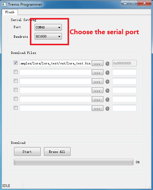
Choose the serial port:
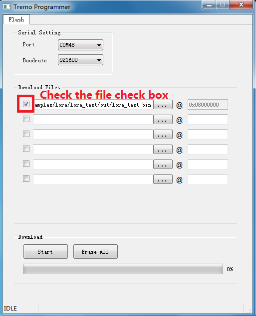
Configure the download file:

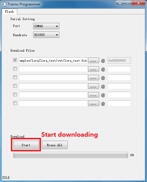
Click the“Start” button to begin downloading:
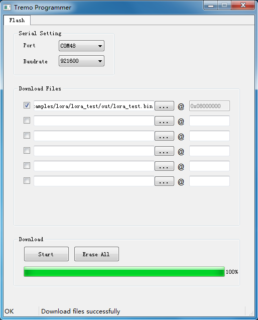
Finish downloading:
4. Q&A
4.1 What is the reason for read response header timeout?
This problem is caused by no response from the development board to be downloaded. Please check the following:
Check if the serial port connection is normal.
Check if the MCU is in download mode. Try to press and hold the SW3 button while pressing the RESET button to reboot the development board.
