ASR6601 Development Board Test Guide
Introduction
About This Document
This document introduces how to test ASR6601 development board to facilitate the developers to better understand the performance of LPWAN SoC ASR6601.
Included Chip Models
The product models corresponding to this document are as follows.
Model |
Flash |
SRAM |
Core |
Package |
Frequency |
|---|---|---|---|---|---|
ASR6601SE |
256 KB |
64 KB |
32-bit 48 MHz Arm China STAR-MC1 |
QFN68, 8*8 mm |
150 ~ 960 MHz |
ASR6601CB |
128 KB |
16 KB |
32-bit 48 MHz Arm China STAR-MC1 |
QFN48, 6*6 mm |
150 ~ 960 MHz |
ASR6601SER |
256 KB |
64 KB |
32-bit 48 MHz Arm China STAR-MC1 |
QFN68, 8*8 mm |
150 ~ 960 MHz |
ASR6601CBR |
128 KB |
16 KB |
32-bit 48 MHz Arm China STAR-MC1 |
QFN48, 6*6 mm |
150 ~ 960 MHz |
Copyright Notice
© 2021 ASR Microelectronics Co., Ltd. All rights reserved. No part of this document can be reproduced, transmitted, transcribed, stored, or translated into any language in any form or by any means without the written permission of ASR Microelectronics Co., Ltd.
Trademark Statement
ASR and ASR Microelectronics Co., Ltd. are trademarks of ASR Microelectronics Co., Ltd.
Other trade names, trademarks, and registered trademarks mentioned in this document are the property of their respective owners and are hereby declared.
Disclaimer
ASR does not give any warranty of any kind and may make improvements and/or changes in this document or in the product described in this document at any time.
This document is only used as a guide, and no contents in the document constitute any form of warranty. Information in this document is subject to change without notice.
All liability, including liability for infringement of any proprietary rights caused by using the information in this document, is disclaimed.
Revision History
Date |
Version |
Release Notes |
|---|---|---|
2020.08 |
V0.1.0 |
First release. |
2020.09 |
V0.2.0 |
Updated some pictures. |
2020.10 |
V0.3.0 |
Updated the pictures of ASR6601SE development board v2.0. |
2021.01 |
V1.1.0 |
Deleted Chapter 1, and move the contents to “About This Document”. |
2021.05 |
V1.2.0 |
Updated Section 1.3. |
1. Preparation
1.1 Hardware
LoRa nodes hardware requirements:
1 ASR6601 development board
1 antenna
1 USB cable
1 PC
1.1.1 ASR6601 Development Board
ASR6601SE/SER development board v2.0 front and back photos are as follows:

The Front View of ASR6601SE/SER Development Board v2.0

The Back View of ASR6601SE/SER Development Board v2.0
Interface |
Description |
|---|---|
USB-UART |
USB |
Power Switch |
Power switch |
Reset |
Reset button |
SW3 |
It’s the Download button pressed to pull up GPIO02 |
SW1 |
It’s the User button pressed to pull down GPIO11 |
JP1 |
Jumper1 |
JP2 |
Jumper2 |
JP3 |
Jumper3 |
JP4 |
Jumper4, which can be used to test the board’s total power consumption |
JP5 |
Connect UART_TX jumper, then select UART0_TX. Reference: Schematics |
JP6 (only used in ASR6601CB development board) |
Connect UART_TX jumper, then select LPUART_TX. Reference: Schematics |
JP7 |
Connect UART_TX jumper, then select UART0_RX. Reference: Schematics |
JP8 |
Connect UART_TX jumper, then select LPUART_RX. Reference: Schematics |
1.1.2 Jumper Connection
When testing ASR6601 development board, please make sure the following jumpers’ state is set correctly.
Jumper |
Connection State |
|---|---|
JP1 |
connected |
JP2 |
connected |
JP3 |
connected |
JP4 |
connected |
JP5 |
connected |
JP6 (only used in ASR6601CB development board) |
Not connected |
JP7 |
connected |
JP8 |
Not connected |
1.2 Software
1.2.1 Development Environment
Customers can use Keil to develop ASR6601. Makefile also can be used for compilation and download. For further details, please refer to ASR6601_Quick Start Guide.
1.2.2 Test Codes
Test codes can be found in the directory of projects\${DEMO_BOARD}\examples\lora\lora_test in SDK. ${DEMO_BOARD} is the corresponding board name. For example, ASR6601SE-EVAL stands for ASR6601SE/SER development board, and ASR6601CB-EVAL stands for ASR6601CB/CBR development board.
1.3 Compilation and Download
Please refer to ASR6601_Quick Start Guide for compilation and download introductions.
2. Tests
There are some AT commands built in test codes, which can be used to test part of functions.
2.1 Power Test
Test Command: With one serial port tool, and run AT command AT+CTXCW=490000000,22 to test the power. Please refer to Section 3.2.6 for parameter descriptions.
Reference Result: 21 dbm
2.2 Sensitivity Test
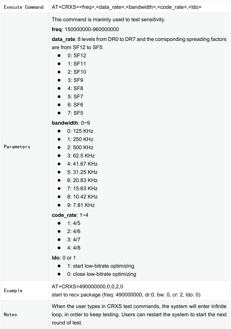
Test Command: With one serial port tool, and run AT command AT+CRXS=490000000,0,0,2,0 to test the sensitivity. Please refer to Section 3.2.3 for parameter descriptions.
Reference Result: -138 dbm
2.3 Power Consumption Test
Unplug the JP4 jumper. Connect the multimeter. Please see the figure below for reference.

2.3.1 TX Power Consumption Test
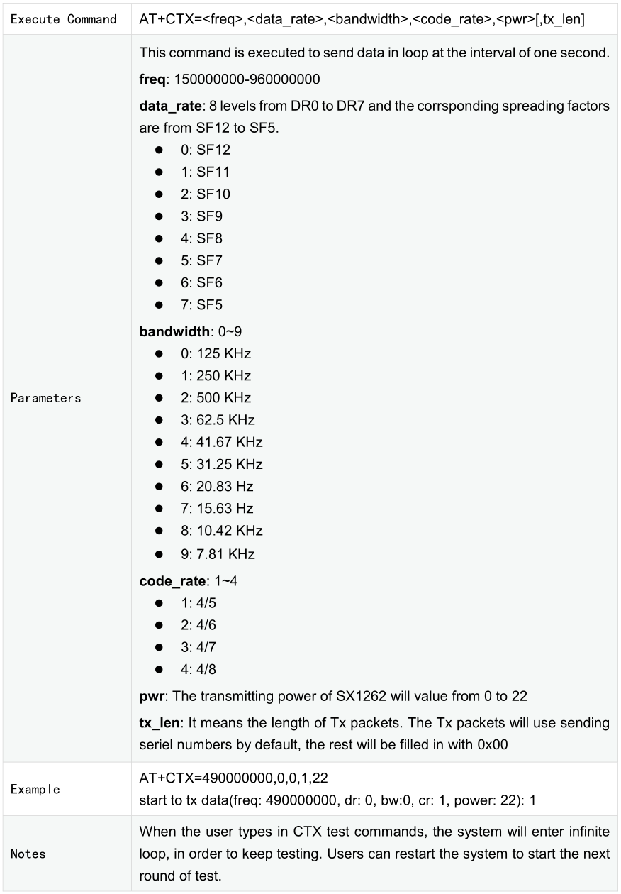
Test Commands: AT+CTXCW=490000000,22
Reference Result: 110 mA
2.3.2 RX Power Consumption Test
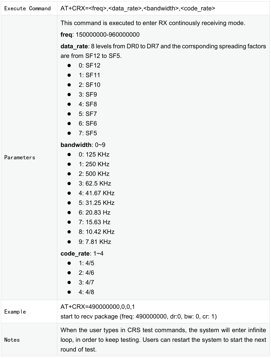
Test Commands: AT+CRX=490000000,0,0,1
Reference Result: 8.9 mA
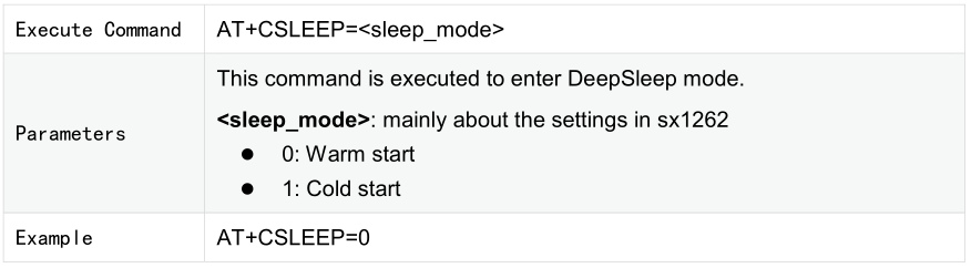
2.3.3 DeepSleep Power Consumption Test
Test Commands: AT+CSLEEP=0
Reference Result: 1.5 uA
3. Basic AT Commands
3.1 Overview
Commands |
Description |
|---|---|
AT+CTXCW |
Send one sustained wave |
AT+CTX |
Send one LoRa package in every other second |
AT+CRXS |
Receive commands. Sensitivity test applicable |
AT+CRX |
Receive commands. Distance test applicable |
AT+CSLEEP |
Low-power test commands |
AT+CSTDBY |
Sx1262 Standby mode test commands |
3.2 Commands
3.2.1 Low-power Test Commands +CSLEEP
3.2.2 Lower-power Test Commands +CSTDBY

3.2.3 Test Commands +CRXS
3.2.4 Test Commands +CRX
3.2.5 Test Commands +CTX
3.2.6 Test Commands +CTXCW
