ASR6601 Test Report
Introduction
About This Document
This document provides the test report for IoT LPWAN SoC ASR6601.
Included Chip Models
The product models corresponding to this document are as follows.
Model |
Flash |
SRAM |
Core |
Package |
Frequency |
|---|---|---|---|---|---|
ASR6601SE |
256 KB |
64 KB |
32-bit 48 MHz Arm China STAR-MC1 |
QFN68, 8*8 mm |
150 ~ 960 MHz |
ASR6601CB |
128 KB |
16 KB |
32-bit 48 MHz Arm China STAR-MC1 |
QFN48, 6*6 mm |
150 ~ 960 MHz |
ASR6601SER |
256 KB |
64 KB |
32-bit 48 MHz Arm China STAR-MC1 |
QFN68, 8*8 mm |
150 ~ 960 MHz |
ASR6601CBR |
128 KB |
16 KB |
32-bit 48 MHz Arm China STAR-MC1 |
QFN48, 6*6 mm |
150 ~ 960 MHz |
Copyright Notice
© 2021 ASR Microelectronics Co., Ltd. All rights reserved. No part of this document can be reproduced, transmitted, transcribed, stored, or translated into any language in any form or by any means without the written permission of ASR Microelectronics Co., Ltd.
Trademark Statement
ASR and ASR Microelectronics Co., Ltd. are trademarks of ASR Microelectronics Co., Ltd.
Other trade names, trademarks, and registered trademarks mentioned in this document are the property of their respective owners and are hereby declared.
Disclaimer
ASR does not give any warranty of any kind and may make improvements and/or changes in this document or in the product described in this document at any time.
This document is only used as a guide, and no contents in the document constitute any form of warranty. Information in this document is subject to change without notice.
All liability, including liability for infringement of any proprietary rights caused by using the information in this document, is disclaimed.
Revision History
Date |
Version |
Release Notes |
|---|---|---|
2021.05 |
V1.0.0 |
First release. |
1. Test Overview
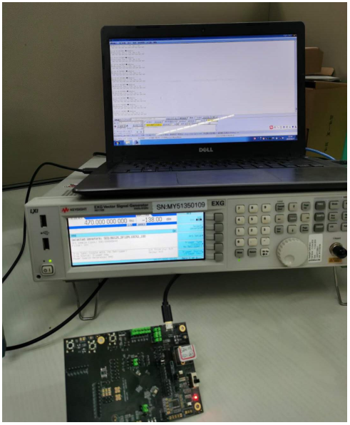
1.1 Hardware
68-Pin ASR6601-SE V1.0 Development Board
1.2 Software
ASR6601 V1.0 SDK
1.3 Equipment
Agilent N5182B and Agilent N9020A
1.4 Test Items and Results Summary
2. Test Implementation
2.1 TX Test
2.1.1 Setup TX Test Environment
2.1.2 Frequency Offset Test
Test Method
Frequency setting:
Set to LoRa CW mode with 470.0 MHz frequency
Set the power to 22.0 dBm
Spectrum analyzer setting:
Center frequency is 470.0 MHz, Span is 2 MHz, Ref amp is 25.0 dBm
Measure the CW frequency with the marker of the spectrum analyzer
Illustration
Test Result
SN |
Set (MHz) |
Test (MHz) |
PPM |
|---|---|---|---|
1# |
470.000 |
469.9980 |
4.25 |
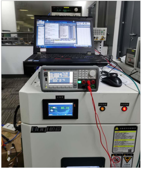
2.1.3 Transmit Power Test
Test Method
Frequency setting:
Set to LoRa CW mode with 470.0 MHz frequency
Set the power to 22 dBm
Spectrum analyzer setting:
Set frequency point at 1st, 2nd, 3rd, 4th and 5th of the basic frequency
Span is 2 MHz (or 5 MHz), Ref amp is 25 dBm
Max Hold mode
Illustration

Test Result
Maximum Transmit Power Test Result
SN |
Frequency (MHz) |
Set (dBm) |
Basic (dBm) |
|---|---|---|---|
1# |
470 |
22 |
21.06 |
2# |
470 |
22 |
20.97 |
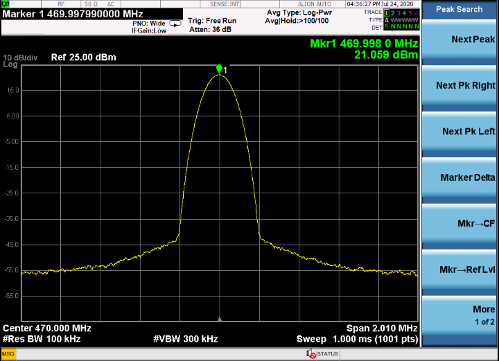
2.1.4 Harmonic Test
Test Method
Frequency settings
Set to LoRa CW mode with 470.0 MHz frequency
Set the power to 22 dBm
Spectrum analyzer settings
Set frequency point at 1st, 2nd, 3rd, 4th and 5th of the basic frequency
Span is 2 MHz (or 5 MHz), Ref amp is 25 dBm
Max Hold mode
Illustration
2nd/3rd/4th/5th Harmonic Test
Test Result
SN |
Frequency (MHz) |
Set (dBm) |
Basic (dBm) |
2nd (dBm) |
3rd (dBm) |
4th (dBm) |
5th (dBm) |
|---|---|---|---|---|---|---|---|
1# |
470 |
22 |
21.06 |
-46.94 |
-50.74 |
-55.80 |
-60.41 |
2# |
470 |
22 |
20.97 |
-45.42 |
-49.57 |
-56.22 |
-59.28 |
2.1.5 Phase Noise Test
Test Method
Frequency setting:
Set to LoRa CW mode with 470.0 MHz frequency
Set the power to 22 dBm
Spectrum analyzer setting:
Maker -> Delta, Function -> maker noise
Span is 2 MHz (or 5 MHz), Ref amp is 25 dBm
Max Hold mode
Illustration
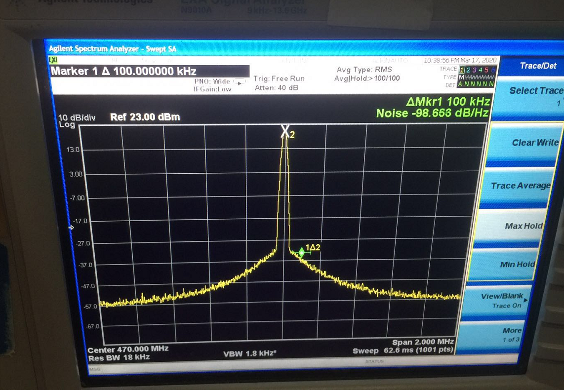
Test Result
SN |
Frequency (MHz) |
ACT (MHz) |
Phase Noise (dB/Hz) |
|---|---|---|---|
1# |
470 |
469.999 |
-98.653 |
2# |
470 |
469.999 |
-99.965 |
2.2 RX Test
2.2.1 RX Test Environment Setup
2.2.2 RX Sensitivity Test
Test Method
Frequency setting:
Set to LoRa RX test mode with 470.0 MHz frequency
Signal generator setting:
Load related waveform for different SF
Measure the SNR threshold as below
RX Sensitivity Test Specification
SF |
BW (KHz) |
Package RSSI (dBm) |
SNR Limit (dB) |
|---|---|---|---|
SF7 |
125 |
<123 |
-7.5 |
SF8 |
125 |
-10 |
|
SF9 |
125 |
-12.5 |
|
SF10 |
125 |
<130 |
-15 |
SF11 |
125 |
-17.5 |
|
SF12 |
125 |
<135 |
-20 |
Test Result

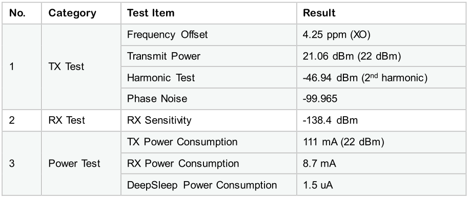
2.3 Power Consumption Test
Test Method
Frequency setting:
Set to 470 MHz frequency under TX, RX, Standby and Sleep mode
Multimeter setting:
Set the multimeter to current test mode
AT Command:
TX: AT+CTXCW=470000000,22
RX: AT+CRX=470000000,0
Deep sleep: AT+CSLEEP=1
Illustration
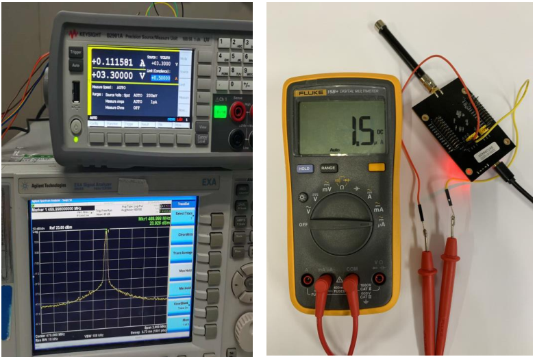
Test Result

Note
The power consumption test result is for ASR6601 SoC with front-end RF.