ASR6601 OTA Upgrade Guide
Introduction
About This Document
This document mainly introduces the OTA upgrade Demo project in LPWAN SoC ASR6601 SDK.
Included Chip Models
The product models corresponding to this document are as follows.
Model |
Flash |
SRAM |
Core |
Package |
Frequency |
|---|---|---|---|---|---|
ASR6601SE |
256 KB |
64 KB |
32-bit 48 MHz Arm China STAR-MC1 |
QFN68, 8*8 mm |
150 ~ 960 MHz |
ASR6601CB |
128 KB |
16 KB |
32-bit 48 MHz Arm China STAR-MC1 |
QFN48, 6*6 mm |
150 ~ 960 MHz |
ASR6601SER |
256 KB |
64 KB |
32-bit 48 MHz Arm China STAR-MC1 |
QFN68, 8*8 mm |
150 ~ 960 MHz |
ASR6601CBR |
128 KB |
16 KB |
32-bit 48 MHz Arm China STAR-MC1 |
QFN48, 6*6 mm |
150 ~ 960 MHz |
Copyright Notice
© 2021 ASR Microelectronics Co., Ltd. All rights reserved. No part of this document can be reproduced, transmitted, transcribed, stored, or translated into any language in any form or by any means without the written permission of ASR Microelectronics Co., Ltd.
Trademark Statement
ASR and ASR Microelectronics Co., Ltd. are trademarks of ASR Microelectronics Co., Ltd.
Other trade names, trademarks, and registered trademarks mentioned in this document are the property of their respective owners and are hereby declared.
Disclaimer
ASR does not give any warranty of any kind and may make improvements and/or changes in this document or in the product described in this document at any time.
This document is only used as a guide, and no contents in the document constitute any form of warranty. Information in this document is subject to change without notice.
All liability, including liability for infringement of any proprietary rights caused by using the information in this document, is disclaimed.
Revision History
Date |
Version |
Release Notes |
|---|---|---|
2020.06 |
V0.1.0 |
First Release. |
2020.10 |
V0.2.0 |
Updated the figures in Section 1.1. |
2021.05 |
V1.1.0 |
Deleted Chapter 1, and move the contents to “About This Document”. |
2021.06 |
V1.2.0 |
Added verified Android phone models in Section 1.1. |
1. Preparation
1.1 Hardware
Hardware requirements are as follows:
2 ASR6601 development boards
2 antennas
2 USB cable
1 USB converter
1 Android cellphone, and the Android phone models verified by ASR are as follows:
HUAWEI Mate 20 Pro, Android 10, EMUI 11.0.0
HUAWEI nova, Android 10, EMUI 11.0.0
HUAWEI Maimang 6, Android 8, EMUI 8.0.0
Xiaomi MIX 2S, Android 9, MIUI 11.0.3
1 PC

Connect the Cellphone to the OTA Dongle Board
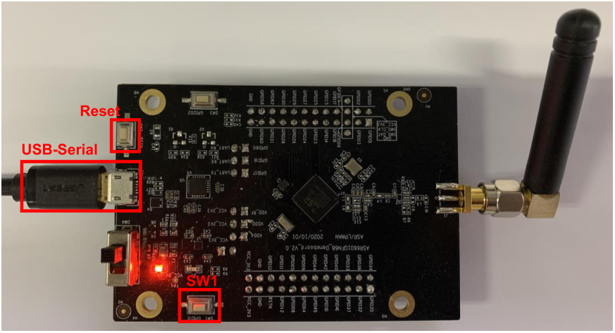
Connect the Target Board to the PC
1.2 Software
1.2.1 OTA Dongle Board Software
OTA dongle code is located in projects\${DEMO_BOARD}\examples\ota\dongle directory. ${DEMO_BOARD} is the name of the OTA dongle board, for example, ASR6601SE-EVAL stands for ASR6601SE development board, and ASR6601CB-EVAL stands for ASR6601CB/CBR development board.
Compile and download the corresponding code to the OTA dongle board.
1.2.2 Target Board Software
There are two parts regarding the target board software: OTA bootloader and APP code.
OTA bootloader
OTA bootloader code is located in projects\${DEMO_BOARD}\examples\ota\bootloader directory. ${DEMO_BOARD} is the name of the target board, for example, ASR6601SE-EVAL stands for ASR6601SE development board, and ASR6601CB-EVAL stands for ASR6601CB/CBR development board.
Compile and download the corresponding code to 0x08000000 address.
APP
APP code is the code needs updates. In this document, we take uart_printf project as an example.
Edit the gcc.ld file in the uart_printf project. Edit the start address of FLASH to 0x0800D000. Then compile the modified project. After the compilation is complete, copy the generated project file (project.bin) to the cellphone.

Linker Script
1.2.3 Cellphone
LoRa OTA APP code is located in projects\ASR6601SE-EVAL\examples\ota\android_app.
Copy apk to the cellphone, then install.
2. Upgrade Process
2.1 Enter OTA Bootloader Mode
Press and hold the SW1 button of the target board, then RESET the board to make it enter OTA bootloader mode.

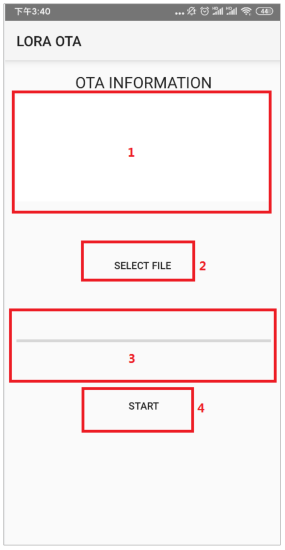
2.2 Open APP
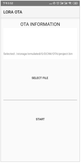
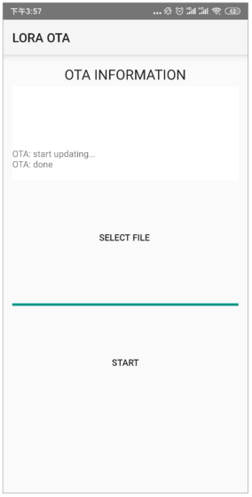
Connect the cellphone and the OTA dongle board via a USB converter. Then open the APP. The main interface is shown as follows:
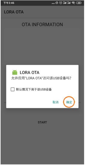
Note
Click “Confirm” if an access prompt appears during the connection.
Explanations about the red marks illustrated above:
Red 1: this area provides relevant information during OTA upgrade.
Red 2: this button is used to select the corresponding upgrade file.
Red 3: this progress bar shows the progress of OTA.
Red 4: this button is used to start OTA upgrade.
2.3 Select the Upgrade File
Click the “SELECT FILE” button and you can see below interface:
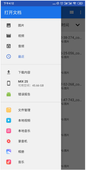
File Management Interface
Enter the directory where the project.bin file is located, and select the bin file:
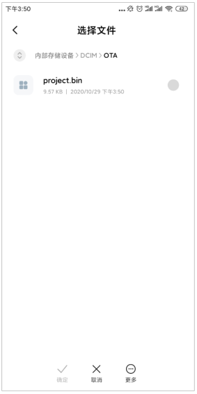
Go back to the main interface. The OTA information area will display the selected bin file:
2.4 Start Upgrade
Click ”START” to start upgrade and it will be shown in the OTA information area.
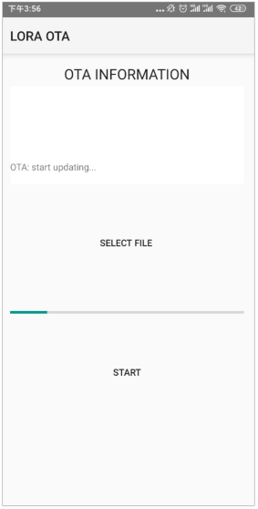
The information area will display “OTA: done” when the OTA upgrade is finished successfully.
Meanwhile, the target board will print:
hello world
3. OTA Dongle AT Commands
3.1 Overview
The relevant AT Commands are as follows:
Command |
Description |
|---|---|
AT+FREQ |
Set frequency rate |
AT+CFG |
Configure parameters |
AT+TX |
Send data |
AT+RX |
Enter receiving mode |
AT+DATA |
Report data after receipt |
3.2 AT Commands Descriptions
3.2.1 AT+FREQ

3.2.2 AT+CFG

3.2.3 AT+TX

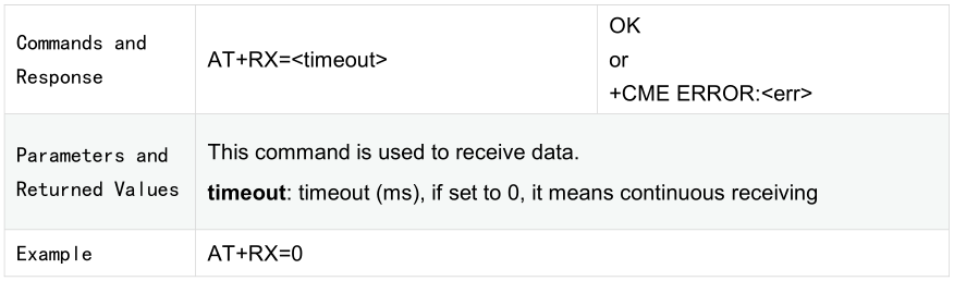
3.2.4 AT+RX
3.2.5 AT+DATA

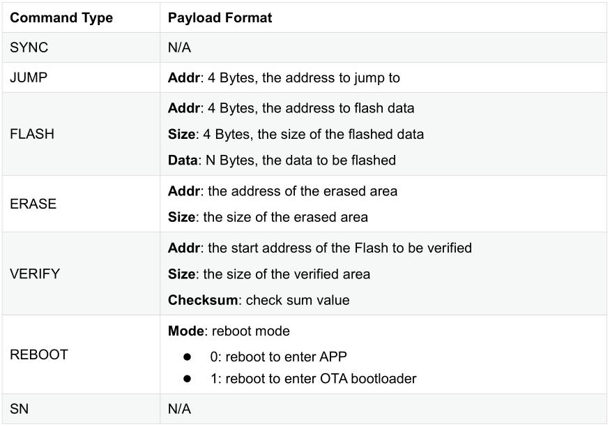
4. OTA Bootloader Commands
4.1 Overview
Command |
Command Number |
Description |
|---|---|---|
SYNC |
1 |
SYNC command tells if the connection is normal |
JUMP |
2 |
Jump command |
FLASH |
3 |
Flash command |
ERASE |
4 |
Erase command |
VERIFY |
5 |
Verify command |
REBOOT |
12 |
Reboot command |
SN |
13 |
Read the serial number command |
4.2 Command Format
4.2.1 Request

Fill in the command number in the “Command” column. The algorithm of Checksum is CRC32.
4.2.2 Response

4.3 Command Payload Format